Looking for how to read engineering drawing CNC guidance? You are in the right place. This guide answers the key questions for engineers.
Why This Matters — how to read engineering drawing CNC
Engineering drawings are the contract between designer and manufacturer. Misreading a tolerance or missing a note can mean an entire batch of parts made to the wrong spec. Even non-engineers who manage procurement or review quotes benefit from understanding what they are approving.
The Three Standard Views — how to read engineering drawing CNC
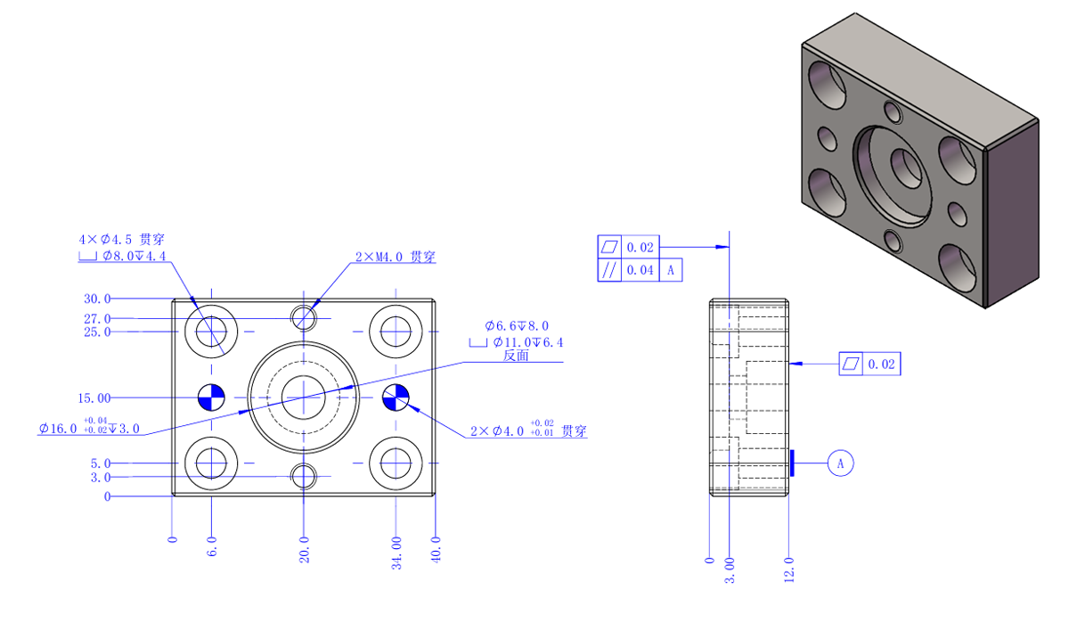
Most drawings show the part from three directions: front, top (plan), and right side. These are called orthographic projections. Hidden features (holes or slots you cannot see from the outside) appear as dashed lines. Reading all three views together gives you the 3D shape. The "section view" cuts through the part to reveal internal features — it is marked with arrows and letters like "A-A."
Dimensions and Tolerances — how to read engineering drawing CNC
Dimensions appear as lines with arrowheads and a number (e.g., 50.000). A tolerance appears immediately after: 50.000 ±0.025, or as a bilateral limit 50.025 / 49.975. The title block (bottom right corner) usually states a general tolerance that applies to all features without explicit callouts — typically ±0.1 or ±0.05mm.
GD&T Symbols You Will See — how to read engineering drawing CNC
GD&T (Geometric Dimensioning and Tolerancing) uses symbols inside rectangular boxes called "feature control frames." Common symbols:
- ⊥ Perpendicularity — a surface must be perpendicular to a datum within X mm
- ∥ Parallelism — a surface must be parallel to a datum within X mm
- ⌀ Diameter — applied to circular features
- ○ Circularity (roundness) — how close a cross-section is to a perfect circle
- ↗ Flatness — how much a flat surface deviates from a perfect plane
- ⌖ True Position — locates a feature (usually a hole) relative to datums within a diameter zone
Datums: The Origin of All Measurements — how to read engineering drawing CNC
Datums are reference surfaces marked A, B, C on the drawing. All measurements are taken relative to datums. Datum A is usually the primary flat face that sits on the machine table. Understanding datums tells you which surfaces the machinist touches first when setting up.
The Title Block
Bottom right. Contains: part name, part number, material, revision letter, drawing scale, general tolerance, finish specification, company name. approval signatures. Always check the revision letter matches the file you sent to manufacturing — old revisions are a common source of errors.
Notes and Special Instructions
Near the title block or near relevant features. Look for: "BREAK ALL SHARP EDGES 0.3mm MAX," "ANODIZE PER MIL-A-8625 TYPE II," "INSPECT 100%." These apply to the entire part or specified features and can significantly affect cost and lead time.
Related Ginwate Resources
- Tolerances Reference — achievable tolerances per process
- Surface Finishes Reference
- GD&T True Position Explained — deep dive on the most common GD&T callout
- Upload your drawing for a quote
References: ISO 2768 General Tolerances and CNC on Wikipedia.
FAQs about how to read engineering drawing CNC
Is how to read engineering drawing CNC right for every project?
No. how to read engineering drawing CNC fits some jobs better than others. We help you pick the right spec for your part. Tell us your load, heat, and budget, and we will steer you to the best choice. Most clients save money by picking the right grade up front, not the most premium one.
How fast can Ginwate ship how to read engineering drawing CNC parts?
For most how to read engineering drawing CNC jobs we quote in four hours. Lead time runs five to ten days for prototypes. Production runs land in two to three weeks. Rush jobs ship in 72 hours when stock is on hand. Send your CAD file to start.
What tolerances can you hold for how to read engineering drawing CNC?
Most how to read engineering drawing CNC parts hold plus or minus 0.02 mm without trouble. Tighter tols are possible with the right fixturing and a final grind pass. We hit ISO 2768-fH on first try for the bulk of jobs. Spec the tols you need, not tighter than that.
Do you offer DFM review for how to read engineering drawing CNC?
Yes. Every quote includes a free DFM review by a senior engineer. We flag hard features, costly tols, and cheaper paths. This pays back fast — most parts get five to twenty percent cheaper after the review. No fee for this service.
Key Takeaways on how to read engineering drawing CNC
The right plastic or metal pick saves time and money. how to read engineering drawing CNC is one piece of the puzzle. Match the spec to the load, heat, and chemicals your part will see. Pick simple geometry where you can. Spec tight tols only where they matter. We are here to help at every step.
Ginwate has shipped how to read engineering drawing CNC parts for hundreds of clients. We work with start-ups and Fortune 500 teams. Our shop runs eight CNC mills and four lathes. We hit lead times of five to ten days for most jobs. Quality is checked at every stage. We back our work with a full quality report.
Want to learn more about how to read engineering drawing CNC? Browse our other guides above. Or send your part files for a free quote. We will get back to you in four hours.

Written by
Chenny
Senior CNC engineer at Ginwate · 20+ years aerospace & medical machining